Mazda 6 Forums banner

How To: Swap 2006-2008 Radio & Info Display into 2003-2005 Mazda 6

1 reading
82K views 42 replies 25 participants last post by  jhulian79  
#1 · (Edited)
#3 ·
I started this last night and it works well, just waiting for the 2007 HVAC controls to arrive and I'm done.

For anyone trying this - to save yourself buying 5 OEM harnesses and 3 harness connecters and removing the wires, just buy 1 "FORD/MAZDA PARROT CONVERTOR LEADS" off ebay which contains all the necessary wires in 1 and makes this job way easier.

Also if your 2007 head unit doesn't come with the HVAC controls, your old 2004 ones are not compatible.
 
#4 ·
I started this last night and it works well, just waiting for the 2007 HVAC controls to arrive and I'm done.

For anyone trying this - to save yourself buying 5 OEM harnesses and 3 harness connecters and removing the wires, just buy 1 "FORD/MAZDA PARROT CONVERTOR LEADS" off ebay which contains all the necessary wires in 1 and makes this job way easier.

Also if your 2007 head unit doesn't come with the HVAC controls, your old 2004 ones are not compatible.
Thanks for the tip on the wiring harness.

Are your HVAC controls manual or auto ? I ran my 2007 auto HVAC controls with no head unit for a while and worked fine. Can't see the LCD readout, but it controls the HVAC system just fine. Might want to try it with the 2004 if you haven't already. Don't connect it to the head unit, just the 2 wire connectors on the back in case you need the heater while you're waiting for parts.
 
#6 · (Edited)
Swap

I am not sure that I understood your post correctly(may be for my bad English)

I have pre-facelifted model, non bose, no navigation.
Next month I will get new radio unit from the facelifted M6 GG1 with whole black panel with cables but without A/C control unit. Also I will get new display.

Do I need to do any additional wiring? The A/C control unit should by the same(I hope it will fit to that panel well).

Here is my updated status :-( need to do wiring
http://forum.mazda6club.com/car-electronics/255512-swap-06-08-radio-into-03-05-mazda-6-a-4.html
 
#14 ·
I know, I know this is an old thread. I can't figure something out and I've been reading and re-reading Nik's blog post, this thread, other threads, and more.

So like Nik/icecreme98, I am installing a 2006 stereo and 10 pin lcd display into a 2005 mazda6. It's non-bose, no navigation, and manual climate control. Ok so according to the diagrams, some of the wires from the radio connector (the white one) connect with the display wires (the 10 pin). What happens to the corresponding wires from the car connector (the red one)? For example, wires 1 & 2 from the display connect to wire 2 from the radio. What do I do with wire 2 from the car connector?

This seems like a dumb question, but I am completely new to installing anything electrical and messing with wires. I had to google what splice means. :|

There are so many helpful and knowledgable people here. I appreciate y'all who respond despite how old this thread is.
 
#15 ·
There are so many helpful and knowledgable people here. I appreciate y'all who respond despite how old this thread is.
I really wish I had paid more attention and taken pictures when I did mine 1.5 years ago. I couldn't get my display to work at all when I first installed it, but then figured it out and thought "I really should have taken pictures and documented that."

Let me peek through some of the diagrams I saved when I did mine and get back to you. With yours being manual hvac, it should be the simplest install to do.
 
#17 ·
Wow, thank you so much! I really appreciate it. When I first started this project, I was really gung ho about it. I knew it wouldn't be easy, but I was confident I could figure it out. Turns out I overestimated my skills and underestimated how confusing wiring is.

Lmk if I can give more info to help you help me. I'll remember to take pictures and upload it so I can hopefully help someone else too.
 
#18 ·
Alright, here's the diagrams I went off, including the one I marked up while I was confused. Before I could get an answer about my confusion, I figured out the problem.

Image


Image


I believe it was this chart that threw me off, I thought it was unclear as to where I was getting wires from and where they needed to go.

Image
 
#19 ·
OK, now that I've looked at them, I remember my issue. I was confused as to which WIRE I needed to connect to for display leads 7, 8 & 9, but I didn't need to connect those to a wire coming from the car, I needed to connect those to the pins on the radio (which are empty pins in the pre-2006 harness in your car).

As for your question:
"What happens to the corresponding wires from the car connector (the red one)? For example, wires 1 & 2 from the display connect to wire 2 from the radio. What do I do with wire 2 from the car connector?"
You leave the wire intact and just peel pack some of the outer cover (shown yellow in my previous post), connect wires 1&2 from the display to the bare wire inside the outer cover, then seal it back up. Pros will tell you to solder everything together, but that's likely beyond your skill level. I would split the wire strands inside the car wire, insert your display wires, then wrap around tightly. After that, wrap it tightly with electrical tape and use a couple small zip ties to make sure it stays wrapped. Electrical tape alone can turn to shit after some time in the heat.

Hopefully my tips give you some clarity. Good luck.
 
#20 ·
You leave the wire intact and just peel pack some of the outer cover (shown yellow in my previous post), connect wires 1&2 from the display to the bare wire inside the outer cover, then seal it back up. Pros will tell you to solder everything together, but that's likely beyond your skill level. I would split the wire strands inside the car wire, insert your display wires, then wrap around tightly. After that, wrap it tightly with electrical tape and use a couple small zip ties to make sure it stays wrapped. Electrical tape alone can turn to shit after some time in the heat.

Hopefully my tips give you some clarity. Good luck.

So you're saying wires 1 & 2 from the display connect to the red harness (the one that connects to the car), not the white (connects to radio)? Or are they all connected together? In this example, four wires total: 2 from the display, 1 from white connector, and 1 from the red.


Thanks for the quick response. I started working on this as soon as I got home from work.
 
#21 ·
Ticonixon2 said:
So you're saying wires 1 & 2 from the display connect to the red harness (the one that connects to the car), not the white (connects to radio)? Or are they all connected together? In this example, four wires total: 2 from the display, 1 from white connector, and 1 from the red.
I guess I'm not sure what the "white connector" is. Been too long since I messed with the radio I guess. I thought the one that is wired into the car has a red plug on it, I don't recall dealing with one that has a white plug. But I'm getting old and my memory isn't what it used to be.

Got any pictures of what you're working with? Would probably jump-start my brain if so.
 
#22 ·
Alright, think I jogged my own memory. I assume you're trying to create one of these harnesses per the original instructions?

Image


I didn't go that route, I had the factory 10-pin wiring come with the new display and directly spliced it into the wire harness in my dash. For the pins that were missing in the original 2004 vehicle harness/plug, I inserted my own wires into those empty pins (# 15, 17 & 12) and was good to go.

Creating the "adapter harness" per the writeup is a clean way to do all your wiring on the bench before doing anything in the car, but I decided to just wire mine directly within the vehicle. A bit more of a pain since you're doing a bunch of splicing and connecting while leaning into your dash, but I survived.

To directly answer your question:
are they all connected together? In this example, four wires total: 2 from the display, 1 from white connector, and 1 from the red.
Yes. For that particular connection, you will be putting 4 wires together. If you had skipped connecting the wire from the "white connector" then no power would flow to the radio.
 
#23 · (Edited)
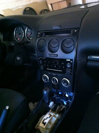
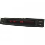
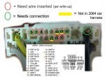
So... I'm about to embark on this soon and have been working on how to get this to work correctly. There is one wire in the 06-08 harness that isn't in our 03-05 cars. This is the "dim cancel" wire. In the 03-05 cars, this function was handled at the display with a button in the upper right hand corner that said "DIMMER".
Image

With the lights on the display would be dimmed for night driving. If you drove during the day with the lights on, you would press the "DIMMER" button on the LCD display to cancel the dim function and put the LCD back to full brightness. If you had an electroluminescant gauge cluster, there is button/stick up in the gauge cluster on the left hand side that would do the same thing for the gauges.

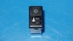
This solution worked, however, to me, and likely a few Mazda engineers, was rather clumsy with two separate buttons to accomplish the desired effect of full brightness illumination. Thus, when they did the facelift starting in 06, they re-did the wiring harness in the car and removed the two switches from the display and the gauge cluster and moved dim cancel switch inside the panel light illumination dimmer control to the left of the steering wheel.
Image

The unfortunate situation for us 03-05 guys who wanted to switch radios is that the way they set up the wiring, with out the dim cancel wire attached to the display, the display is full brightness all the time weather the lights are on or not. Not a big deal during the day with the lights on, but at night it can be pretty bright with the LCD yelling at you from the center of the dash.

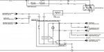
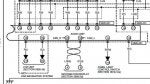
This would bug the snot out of me so I started studying the 06 wiring diagram to see if I could figure out a solution for our 03-05 cars. Here's a picture of the wiring diagram from the 06-08 cars for the panel dimmer switch shown above.
Image

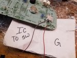
If you look at the panel light control, there's a switch in there on the upper left. One side of the switch goes to ground, and the other goes out and branches into three wires: one goes to the instrument cluster, one goes to the radio display (that's the one that shows up in the wiring diagram photos above), and the third goes to the info display. With a little bench testing, I found out that if you connect the wire coming out of the back of the info display labeled dim cancel to ground, the LCD will dim when you turn the lights on. If you wanted to restore the ability to turn that on and off, you'd need to connect that wire to a switch first and then to ground. Toggling your switch would allow the LCD to toggle between full brightness and the dimmed level when the lights were turned on.

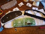
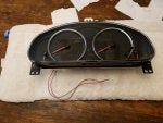
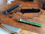
I'm working out what I'm going to do still, but the plan at the moment is to get into the gauge cluster and connect a jumper to the printed circuit board at the location of the "dim cancel" switch in my cluster so that switch will control both displays. This is how it works in our 2011 Mazda 3. This part of the project is a ways off, but I'll try and circle back with a finished set up.

HAPPY MODDING!
 

Attachments

#24 · (Edited)
I wanted to clear up one more thing with regards to the yellow "not in 2004 car harness" photo here...
Image

In this photo, it says that the CAN+ and CAN- are not in the 2004 harness. This is correct, however, in the 2006-2008 harness it isn't there either. I wanted a clean install so I went to the junk yard and pulled the radio from a 2007 6 and clipped the radio harness as far back as I could get into the dash. In researching where the CAN bus signal comes from, it actually comes from the radio to feed the LCD info display.

Here's my harness cut... the big plug goes to the radio, and the smaller one near the top feeds the info display. Right at my hand there's a branch between the main harness and then it splits to the two connectors
Image

A close up of that harness cut shows that the CAN+ and CAN- wires (blue and grey) come OUT of the radio plug and travel back down the harness, and then feed up into the LCD info screen socket.
Image

and a close up of the two wires...
Image


This was a confusing detail in the OP's write up. People were having trouble locating the CAN bus signal in the wiring harness. As it turns out, the factory grabbed that CAN signal for the LCD from the radio.
Image


Hopefully this clears up some of the confusion.
 

Attachments

#25 · (Edited)
LCD Dim cancel from the 03-05 cluster to 06-08 LCD

So I've started the process of getting the dim cancel to work on the 06-08 LCD using the cluster dim cancel switch. The first part of the project was to remove the cluster and find the PCB mounted switch. Once I found that, I had to get that signal out of the cluster so that I could then use it to cancel the DIM on the LCD.

Image


Here are my soldered wires on the back of the PCB connected to the switch. I used some jumpers I found that go from both sides of the switch.
Image


As it turns out, this is not a simple switch. It's 5v+ at all times and when you activate the switch it closes to ground and that tells the cluster to cancel the DIM or vice versa. It would be a fair amount more simple if it was a simple switch, but it can be isolated with a relay if needed.

Here's what the panel looks like all buttoned back up with the two leads hanging out of the back.
Image


In my research for this project, I determined that I'd need momentary soft latching switch or an integrated circuit logic switch. Both of which require a minimum of 5v to operate. So, I looked on the schematics I have for the LCD panels and found a place to pick up 5v that is active anytime the battery is connected on the car. I then soldered on a lead to bring out of the LCD so I can power my switch.
Image


Here are the two soldered leads. The photo is a bit close up so it's hard to see them, but the black ground wire is on the left and the red wire is on the right and both are behind the 10 pin connector
Image

Here's the LCD all back together and connected to positive battery power as if the car was turned off after driving. The meter is showing 5v. (Sorry these next two are upside down. I could not fix it on my phone or after I uploaded it)

Image


Here's the LCD powered up as if it was in the car and you were driving (again sorry for the upside down)
Image

I then had to build a latching switch. This is my first attempt, but it presently does not operate on the LCD's 5v very well. I think some modification to the resistor values is needed. However, the more concerning issue is that the 5v is not enough to power the solid state relay chip. The video here shows it working from the 9v I used to develop it. I also have the "dim cancel" state backwards in the video. When the LED on my circuit is off, the dim has been canceled and the LCD is at full bright. When the LED on the board is on, the LCD is dimmed like it does when the headlights are on.

Unfortunately, I'm not yet sure how to solve the low power in the circuit. I'm have another circuit which works by closing to ground when it's on. This will allow me to remove the relay from the circuit which is one of the issues and will generally simplify things. I'm also looking into a full logic control solution which will be MUCH easier to work with as the wiring will all stay the same, and I can reprogram the chip to do different things based on the state of each wire. The logic control is likely how mazda has it built in their circuits.

Stay tuned for updates!
 

Attachments

#28 ·
Hello everyone,
I'm new here and I would like to ask you for help on a subject similar to this conversation.
I installed, that is, a technician recently installed an Android 8.1 multimedia system purchased on AliExpress on my Mazda 6. The system works, the sound is good, the steering wheel controls and the reversing camera also work well.
What does not work is the Info Display, because there was no cable to connect it, in the set of cables that came with the system.
The Info Display has a 16-pin connector and the Android system, which the image shows, has the set of connections shown in the diagram.
Can someone help me to overcome this difficulty? That is, which cable, if any, to get the connection and have the Info Display working again?
Thank you very much in advance to everyone.
242348
242349
242350
 
#33 ·
Hello everyone,
I'm new here and I would like to ask you for help on a subject similar to this conversation.
I installed, that is, a technician recently installed an Android 8.1 multimedia system purchased on AliExpress on my Mazda 6. The system works, the sound is good, the steering wheel controls and the reversing camera also work well.
What does not work is the Info Display, because there was no cable to connect it, in the set of cables that came with the system.
The Info Display has a 16-pin connector and the Android system, which the image shows, has the set of connections shown in the diagram.
Can someone help me to overcome this difficulty? That is, which cable, if any, to get the connection and have the Info Display working again?
Thank you very much in advance to everyone.
Hi Chizen
There are a lot people, which had made this change before successfully, me too. It depends a little bit on the specific version (year of building) of your Mazda 6. On the picture it looks like your is from 2005 or earlier? If so the easiest solution would be to change the Info-Display to a newer one (2006 to 2010) that can handle the CANBUS signals. And if you haven't already done, you need to change the small pcb board behind the clima controls. Mine is from EZoneTronics and works pretty fine.
And last but most important you need to create a wire to connect the infodisplay by you one as shown in the picture.
Image

The connection on the display has to be as you can see here:
Image

Probably the 'Dimm cancel' will not exist in your harness, so you can connect it to GND (ground) to enable the dimm (reduced brightness) of the display when turning on the lights. Much nicer at night than full brightness. I built an adapter which I plugged between the car and radio connector:
Image

So thats it. Hope that will help. If there are any further questions, don't hesitate to ask.
Best regards
Robert

PS: finally it looks like this in mine:
Image
 
#29 ·
You cant pull the factory radio and have the display work.
 
#30 ·
Thank you TalonTsi90. So, there is really no way ...
I don't know much about this, but I was hopeful that it was possible due to the answer of the authorized Mazda dealer in my city to the same question: "The instrument panel has a microprocessor that calculates the ambient temperature, the distance traveled, the fuel consumption and the remaining fuel. This information is then sent to the audio unit via a CAN connection (terminals 1O and 1Q of the audio unit), and then the audio unit transmits this data to the information display.
The biggest difficulty in this case is that there is no information in the workshop manual regarding the signals that are transmitted individually on each pin (16 in total) in the connection between the audio unit and the information screen. "
I would like to hear more opinions on this topic.
Thanks in advance.